Ask how much storage fits on a site and every layout tool has an answer. Ask whether that layout survives the fire marshal, the setback rules, and the grid operator, and most go quiet.
The gap between those two questions is where BESS projects lose money. A container arrangement that maximizes megawatt-hours per square meter is worthless if the exposure setbacks are short, the fire lane does not close, or the energy per group exceeds what the local authority allows. Finding that out during permitting means redesign, and every deliverable downstream of the layout, cabling, single line diagram, pads, economics, is rework.
This study takes the opposite route: a 15.2 MW / 15.21 MWh BESS designed in 11 steps where the NFPA 855-2023 safety framework was the primary design criterion, not a final check. Setbacks, group separation, energy limits, and the fire lane shaped the layout from the first line. The compliance report came back all clear before anything went to permitting.
The project is the storage side of a larger design: the site and its 19.65 MWp PV plant were designed first, from terrain analysis to the single line diagram, and this study covers only the storage. The project jurisdiction has no dedicated fire code for BESS yet, so NFPA 855 was adopted as the safety framework and the local requirements were written over it.
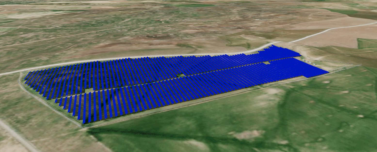
The finished design: 15.2 MW / 15.21 MWh, 4 Sungrow PowerTitan 2.0 containers, AC-coupled, on the real site model.
Start with the ground: area selection
The BESS zone was not picked by eye. The slope and drainage analysis from Part 1 had already identified a flat, drainage-safe plateau with weak PV yield, sitting on the substation side of the site. That 5,847 m² area became zone BESS-A1: flat ground for the containers, outside the drainage corridors, and next to the point of interconnection so the AC cable run stays short.
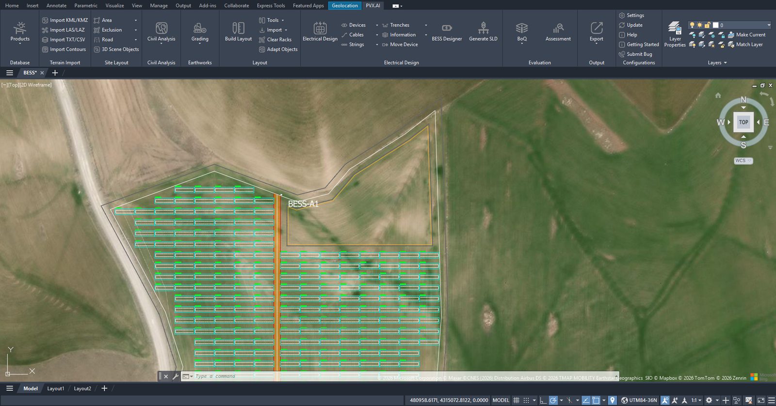
Zone BESS-A1. A flat area with weak PV yield converted to storage: better land use, shorter AC runs.
This decision looks like siting. It is actually the earthworks budget, as the pad grading table will show later.
Draw the perimeter before the units
The first geometry drawn inside BESS-A1 was not a battery container. It was the security fence, checked on the 3D terrain model. The fence line controls access and, more importantly, becomes the geometric reference for everything NFPA 855 asks about: exposure lines, setback measurements, and the fire lane. The access corridor was positioned for emergency vehicle approach from the start.
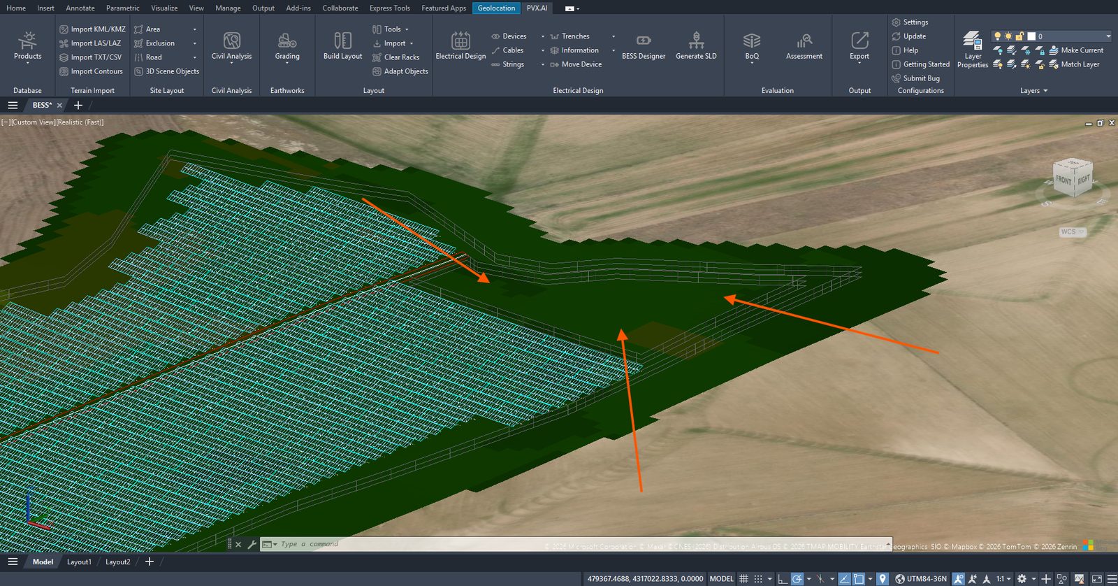
The perimeter fence on natural ground. This geometry is the input for the setback and fire lane calculations that follow.
Define what you are protecting: exposures
NFPA 855’s design logic starts by defining what the storage could endanger. Around BESS-A1, four exposures were tagged directly on the drawing: two lot lines and two public ways, converted from polylines and tagged in the BESS designer. From this point on, setback distances are measured to concrete geographic lines, not abstract rules, and every compliance check runs automatically against them.
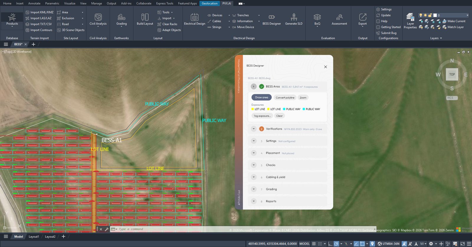
Four tagged exposures. Setbacks and the noise assessment measure to these lines.
The rule set, with the local authority written over it
NFPA 855-2023 was selected as the rule set, with the fire lane width referenced to IFC 2021. Then the local authority’s requirements were applied over the presets from a single panel:
| Rule | NFPA 855-2023 preset | AHJ override applied |
|---|---|---|
| Exposure setback | 3.048 m | 5 m |
| Unit group separation | per code | 2 m |
| Energy per group | per code | 16,000 kWh |
| Remote location threshold | per code | 35 m |
| Fire lane width | IFC reference | 6 m |
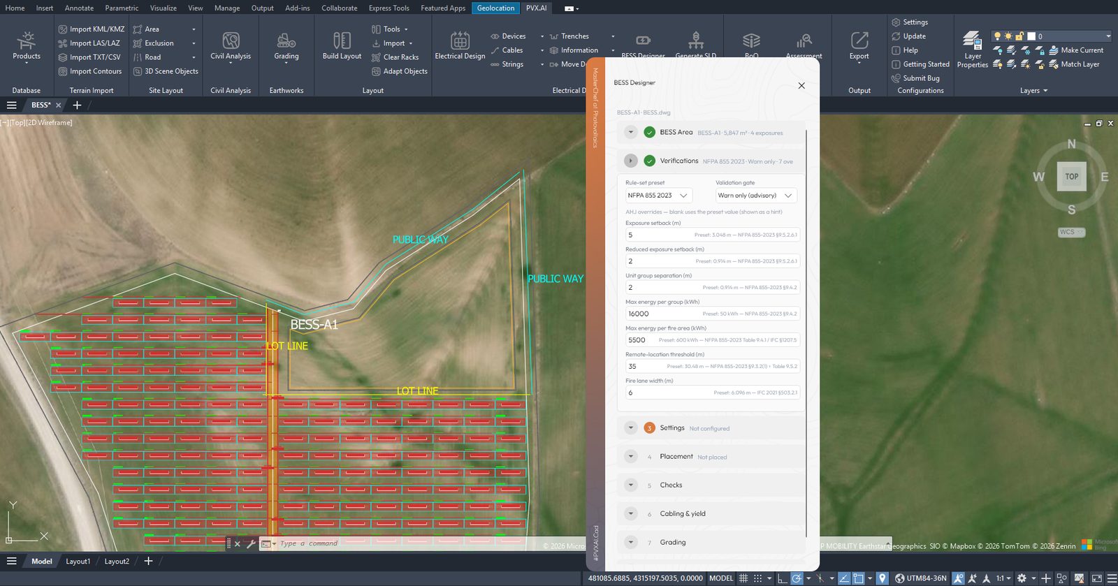
Code presets plus local overrides in one versioned, traceable source. The validation gate ran in warn-only mode during design.
This is the step most workflows do on paper, in a spreadsheet nobody versions. Collecting the effective rules in one place means the layout, the checks, and the permitting package all reference the same numbers.
Configure the battery system around usable energy
The storage unit is the Sungrow PowerTitan 2.0 ST5015UX, an LFP container with 5,015 kWh nameplate and 4,514 kWh usable energy at 90% depth of discharge. The architecture is AC-coupled with 5 m spacing between units. Two decisions matter here: usable energy, not nameplate, became the single input for layout, compliance, and report calculations; and an augmentation projection over 20 years at 365 cycles per year reserved pad space for future units up front.
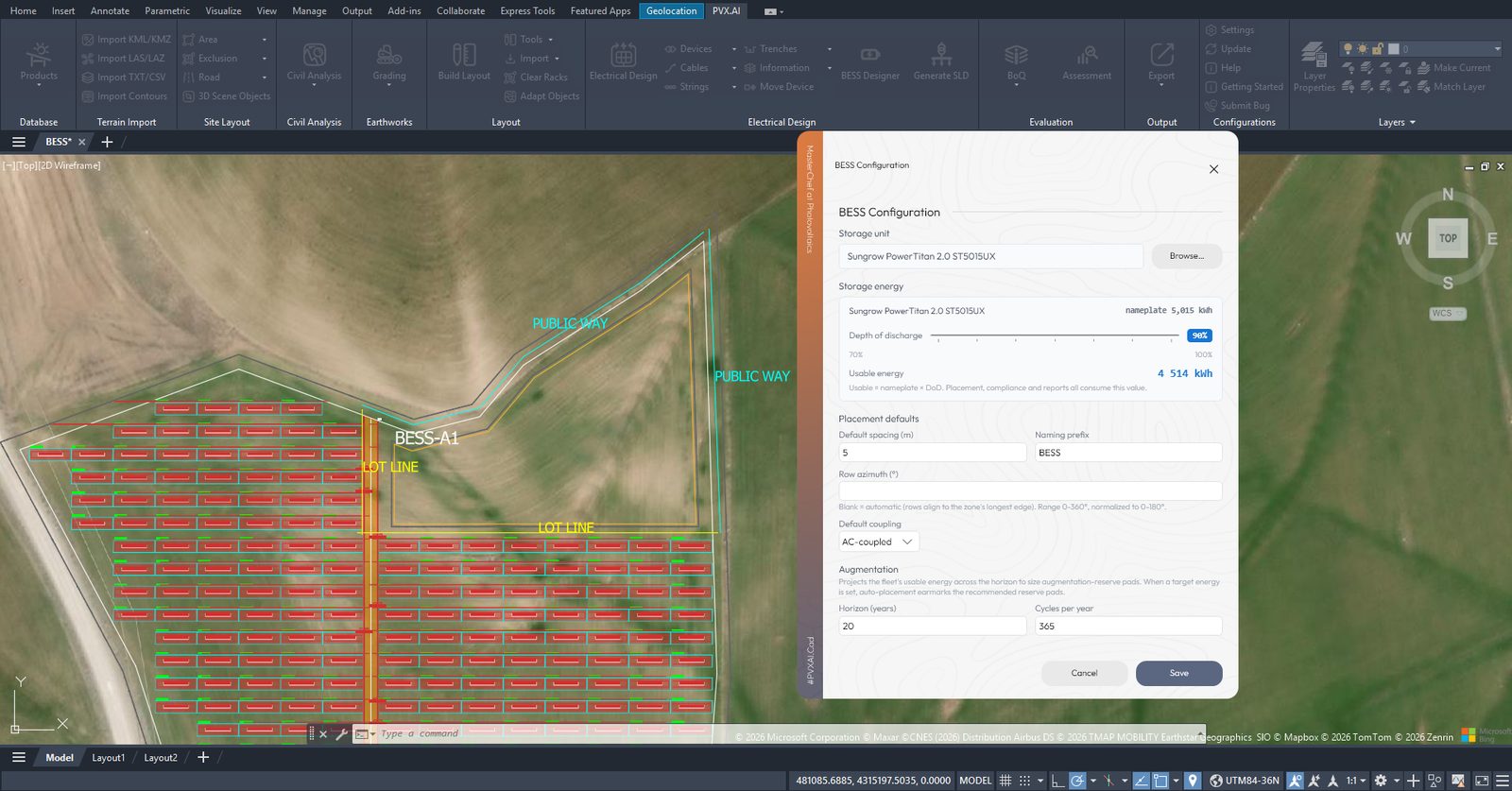
Container configuration: 4,514 kWh usable per unit at 90% DoD, with a 20-year augmentation projection.
On the electrical side, the 19.65 MWp DC plant runs 52 Sungrow SG350-HX inverters at a 1.30 DC/AC target across three transformers (18/18/16). The tool flagged inverter totals exceeding transformer ratings in real time; the oversizing was recorded as a deliberate, documented decision rather than discovered later.
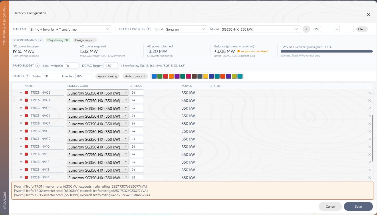
Transformer loading warnings surfaced at design time. Oversizing is a documented decision, not a surprise.
The first safety check: all clear
Four containers were placed and evaluated against the effective rule set. Result: no violations. The effective rules table lists every value as an AHJ override, the energy limit per fire area sits at 21,000 kWh, and two advisory findings estimate noise at the lot line at 47.5 and 47.2 dB(A), comfortably below the 55 dB(A) project threshold but flagged early enough to plan barriers or distance if requirements tighten.
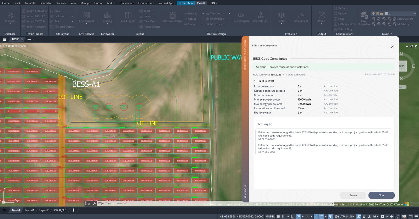
The compliance report: all clear on NFPA 855-2023 with AHJ overrides, at design time, not during permitting.
Pads that move almost no earth
Each container and PCS skid sits on a graded pad with embankment side slopes. The four pad elevations run 993.09 to 993.86 m. Total cut: 1.2 m³. Total fill: 1.2 m³. Net earthworks: 0.0 m³. The flood check returned no findings.
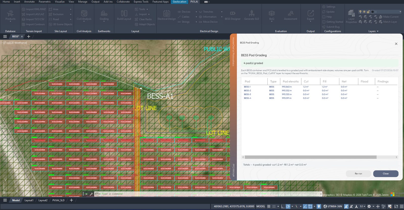
Four graded pads, 0.0 m³ net earthworks. This table is where the terrain-led area selection pays off.
That zero is not a rounding trick. It is the area selection decision from the first step showing up in the earthworks budget. Pick the BESS zone by slope and drainage analysis and the pads settle onto natural ground; pick it by eye and the same table can carry five figures of grading cost.
The single line diagram confirms the sizing
Cabling was generated and the single line diagram produced automatically from the design data: 15.2 MWe / 15.21 MWh, three transformers, 52 inverters, 1,239 strings, four BESS blocks AC-coupled to the MV busbar. Voltage levels run 1,500 V DC, 800 V AC at the inverter output, and 36 kV at the grid. The match between power and energy on the diagram is the numeric confirmation of the ≈ 1C sizing.
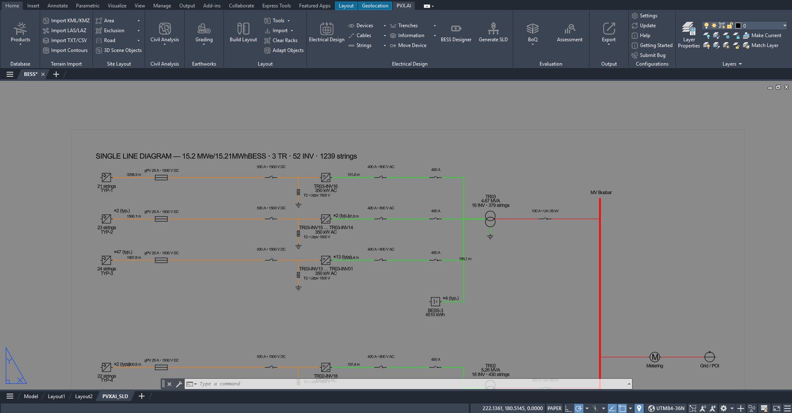
The SLD is generated from design data, so there is no gap between the drawing and the calculation behind it.
Why 1C: the regulation that sized the project
The rule that sized this project is not the US fire code. It is the grid connection regulation of the project’s market. Licensing conditions for storage-backed plants there require that generation capacity does not exceed the storage unit power, and grid connection criteria expect the storage unit to discharge at full power for one hour on system operator request.
That is the rationale for pairing a 15.2 MW connection with 15.21 MWh of energy: a ≈ 1C ratio, full discharge in one hour. The two frameworks divided the work cleanly:
| NFPA 855-2023 | Grid storage regulation | |
|---|---|---|
| Role | safety and layout | sizing and capacity |
| Core requirement | setbacks, group separation, energy limits | battery power equal to connection capacity |
| Discharge requirement | not defined | full power for 1 hour (1C) |
| Design impact | 4-unit layout, 6 m fire lane | 15.2 MW matched with 15.21 MWh |
The natural 0.5C to 1C operating band of LFP container units matches the discharge requirement, so the technology choice complies by itself. And because the sizing rests on regulation, the investment case and the licensing application talk about the same numbers.
Economics and 3D review from the same data
A BESS valuation analysis was requested with inputs auto-filled from the placed units: 15,120 kWh analysis capacity, 13,680 kW charge and discharge power, 88% round-trip efficiency, 90% DoD, 5% reserve SoC. Hourly price series, battery aging, and charge-discharge strategy modules run on the same design data, consistent with the 20-year augmentation plan.
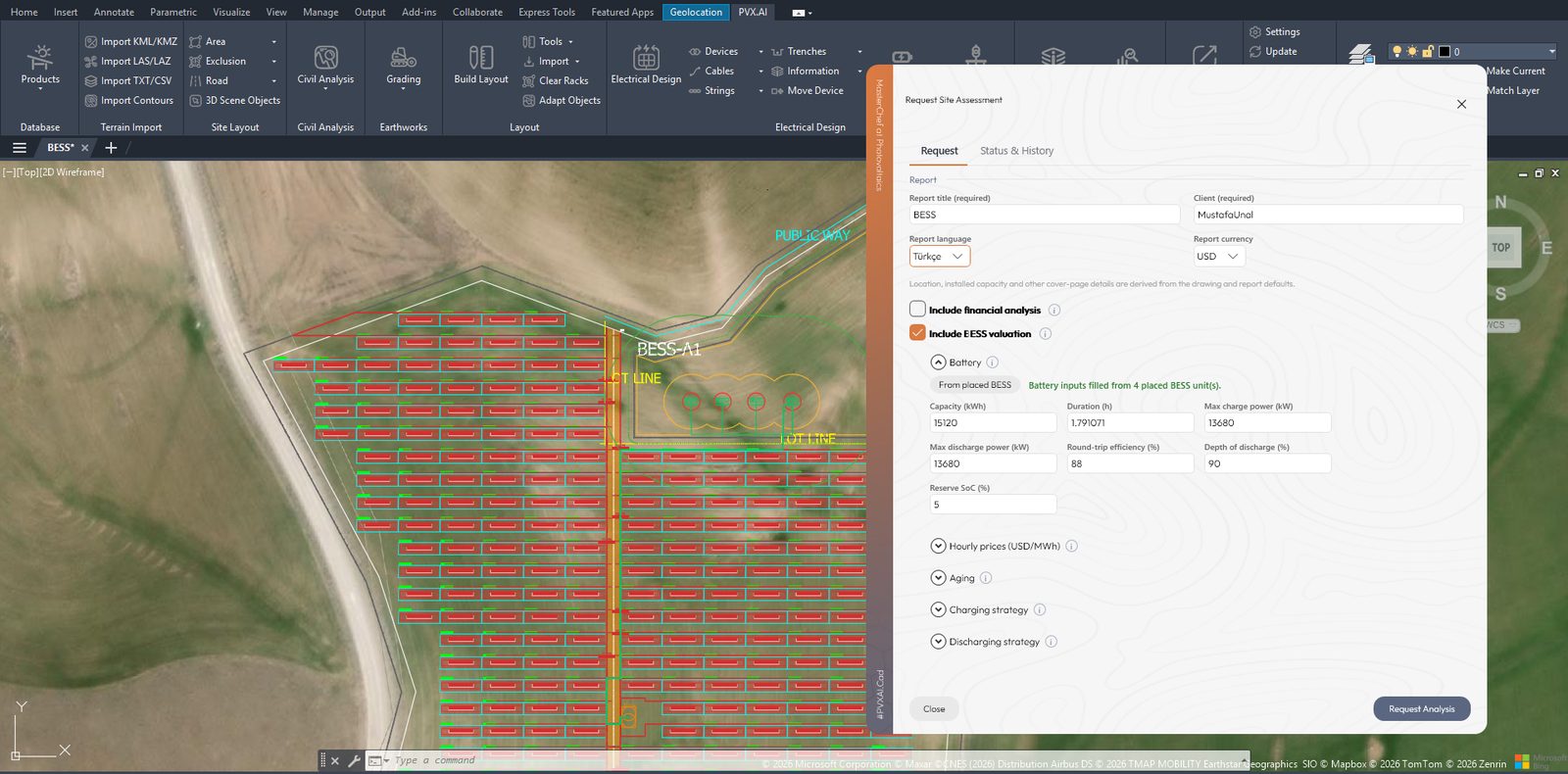
The economic valuation requested in one flow, without detaching from design data.
Finally, the completed design was published to a web viewer: 1,239 racks, roughly 32,214 modules, the containers, and the perimeter fence in a single 3D scene on real topography, with a date and time slider running the shading simulation. Stakeholders review the model in a browser; no CAD files change hands. The simulation also visually confirmed the shade-free location of the BESS area.
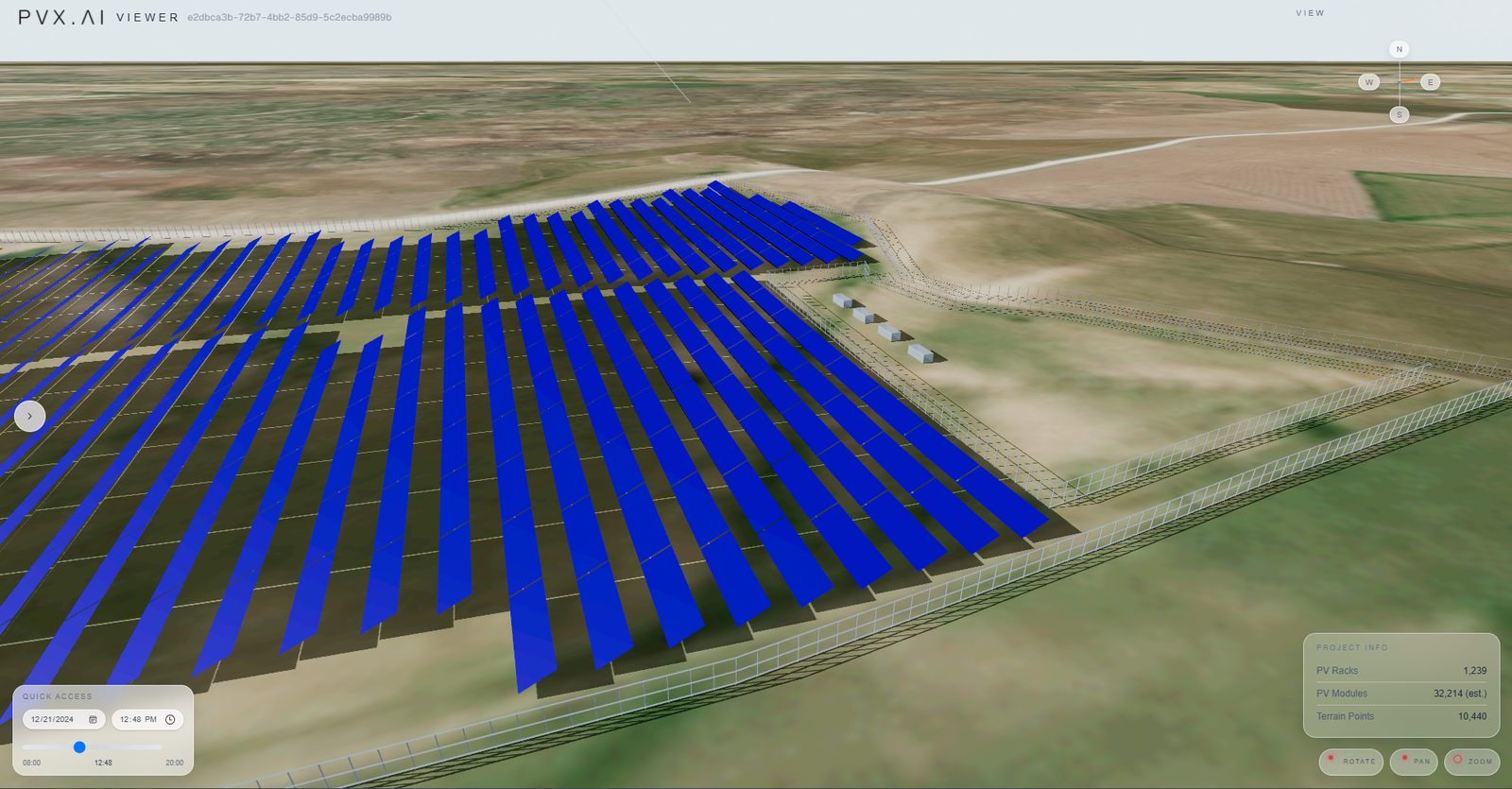
The whole design, shared as a link.
What to take away
- Safety rules were defined at the start and the layout derived from them. The compliance check confirmed the design; it did not redesign it.
- AHJ overrides went over the code presets in one versioned panel, so design, checks, and the permitting package reference the same effective rules.
- Terrain-led area selection zeroed the pad earthworks: 1.2 m³ cut, 1.2 m³ fill, 0.0 m³ net.
- Regulation set the sizing: 15.2 MW paired with 15.21 MWh is the grid regulation’s 1C requirement expressed as a design decision.
- The SLD, the economics, and the 3D review all derive from one design dataset, so the numbers agree with each other by construction.
A BESS layout that only answers “how much fits” is a drawing. One that answers “what gets approved and built” is a design. The difference is whether the safety framework is an input or an afterthought.
PVX.Cad’s BESS designer treats fire code rule sets, exposures, and fire lanes as first-class design objects and verifies compliance while you design. If you are laying out storage this quarter, see it on your own site.
Related reading: BESS peak shaving and clipping economics and the terrain-first methodology.