PVX.Cad includes an MCP server. Connect an AI assistant such as Claude Desktop and it can run the design tools in your AutoCAD: read the drawing, run soil analysis, grade the terrain, place racks, design the electrical, and export the report. You type what you want in plain English. The assistant makes the tool calls. The work happens in your DWG, in your AutoCAD, on your machine.
This post shows what that looks like in one session, lists what the assistant can run today, and explains what it will not do without your say-so. Every number is read off the screen.
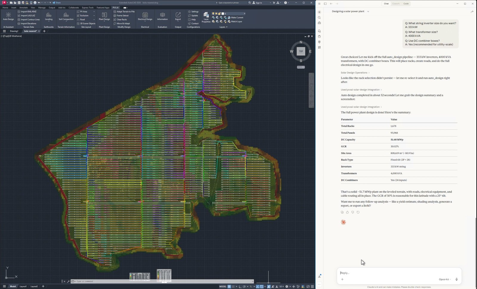
AutoCAD on the left, Claude Desktop on the right. The layout, roads, and cabling on the left were drawn by tool calls the assistant made on the right.
What an MCP server inside CAD means
MCP is the Model Context Protocol, an open standard for connecting AI assistants to software tools. A program that exposes an MCP server publishes a list of tools. Each tool has a typed schema: what it does, what inputs it takes, and whether it changes anything. The assistant reads the schemas, picks an operation, fills in the parameters, and the program runs it and returns the result as data.
PVX.Cad is that program. The server starts with the plugin and publishes the same operations the ribbon buttons run: terrain import, PV area conversion, soil analysis, earthworks, rack selection and placement, stringing, inverter and combiner placement, roads, cable routing, analysis, and exports. The assistant does not draw racks itself. It asks PVX.Cad to place them, and the placement engine does the work with the same rules and the same terrain it uses when you click.
Two things follow from that. The result in the drawing is a real PVX design, so every downstream step works on it: collision analysis, earthworks, exports, PVsyst hand-off. And the assistant can read the drawing back after each step, which is how it knows what to ask you next.
One session, five screens
The screens below come from one Claude Desktop session against PVX.Cad in AutoCAD 2026, on an 81 hectare site with terrain loaded. They were captured on an earlier build, so the tool names shown in the chat differ from the current ones. The operations are the same.
1. It reads the drawing first
The opening instruction was one sentence: design a power plant with the PVX solar design tools. The assistant queried the drawing before proposing anything.
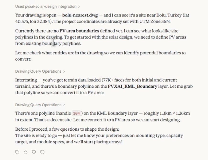
What it found: terrain loaded, one boundary polyline on the KML boundary layer, roughly 1.3 km by 1.26 km, no PV areas defined yet. It then asked the first design question: fixed tilt or single-axis tracker.
That is the pattern for the whole session. Query, report, ask, act. The assistant proposes; the engineer decides.
2. Soil analysis before a single rack
The engineer answered with a different request: run a soil analysis first. The assistant converted the boundary to a PV area and ran it.
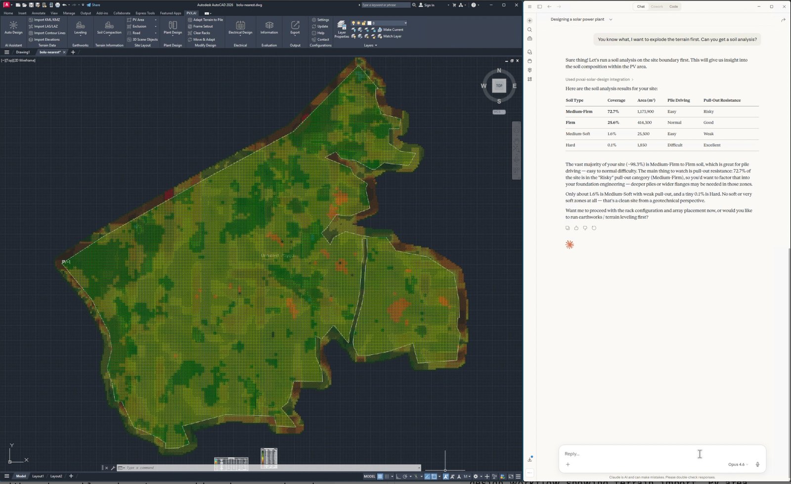
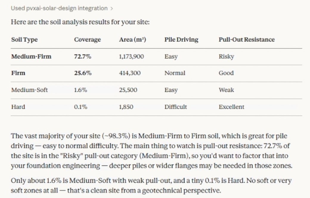
The soil table as the assistant returned it. Medium-Firm covers 72.7 percent of the site, 1,173,900 m², easy to drive but risky on pull-out. Firm covers 25.6 percent, 414,300 m², with good pull-out. Medium-Soft 1.6 percent, Hard 0.1 percent.
The assistant read the table back in words: 98.3 percent of the site is Medium-Firm to Firm, good for pile driving, and 72.7 percent sits in the risky pull-out class, so foundation design should account for it. That is a design note delivered before any rack exists, from data PVX.Cad already had in the drawing.
3. Earthworks at 10 degree limits
Next instruction: level the terrain, go with the minimum. The assistant ran earthworks with 10 degree slope limits in both the north-south and east-west directions. The run took about 1.5 minutes. It then pulled the cut and fill volumes and set the view so the result was visible.
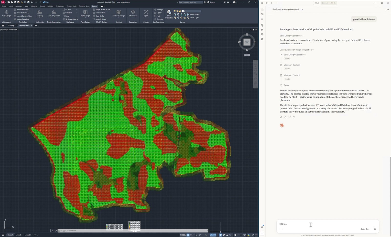
The cut and fill map after the run. The comparison table is in the drawing too. The assistant then asked whether to proceed with rack configuration and placement.
4. Rack and electrical, three questions
The engineer asked it to hide the cut and fill layers and set up the auto design. The assistant froze the layers, then listed what the pipeline needs before it runs: a rack, an inverter size, a transformer size, and optional settings for DC combiners, strings per rack, and road width.
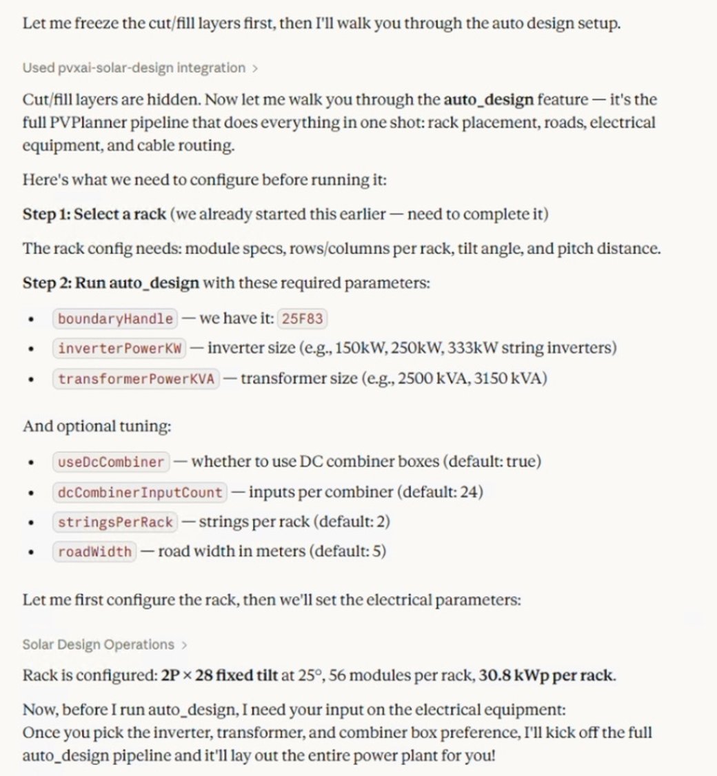
The rack it configured: 2P by 28 fixed tilt at 25 degrees, 56 modules per rack, 30.8 kWp per rack. Then three questions: inverter size, transformer size, DC combiners or not.
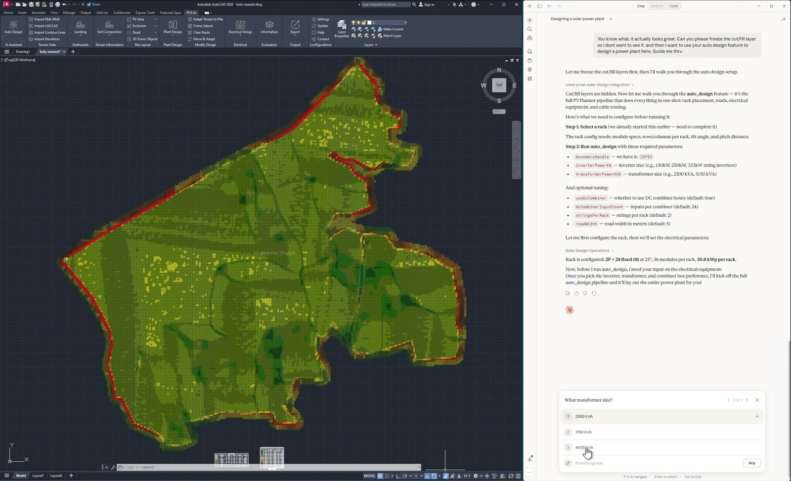
The questions come as choices. The engineer answered 333 kW string inverters, 4,000 kVA transformers, DC combiners yes.
5. The full plant in about 52 seconds
With the three answers in, the assistant ran the auto design pipeline: rack placement, roads, electrical equipment, cable routing.
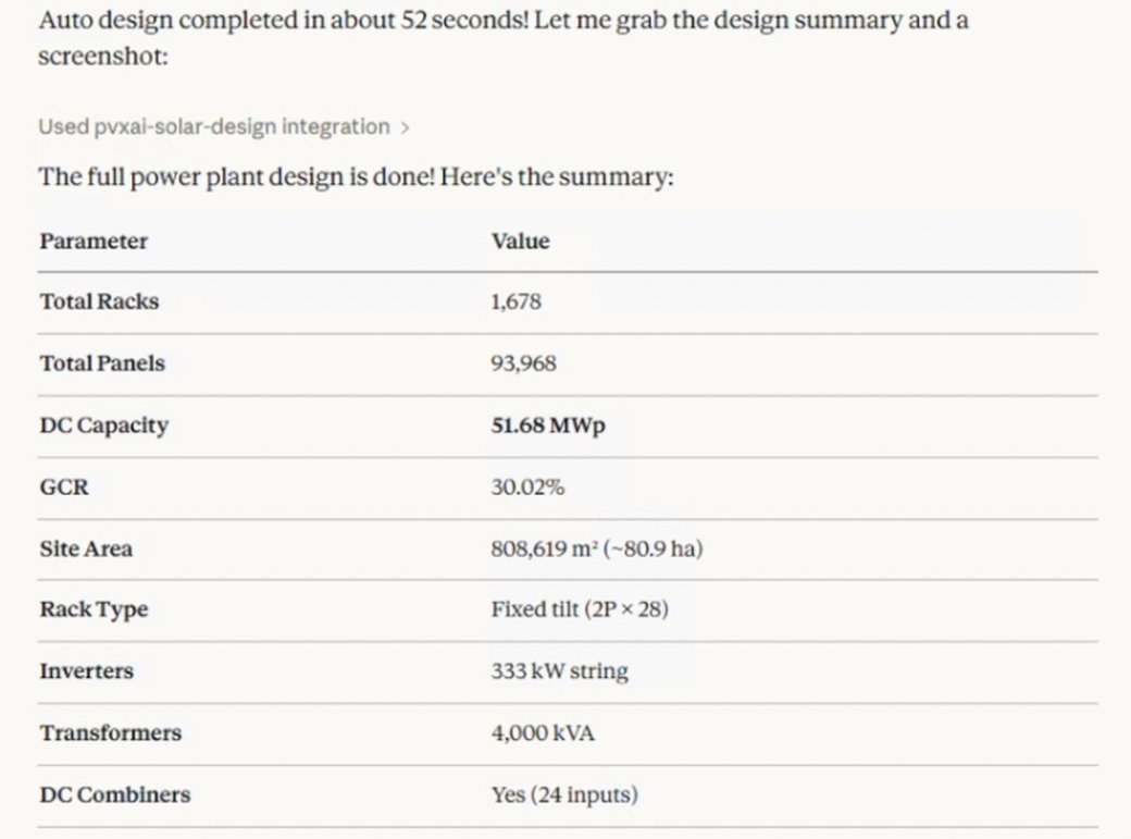
Auto design completed in about 52 seconds. 1,678 racks, 93,968 modules, 51.68 MWp DC, GCR 30.02 percent on 808,619 m². Roads, 333 kW string inverters, 4,000 kVA transformers, DC combiners, and cable routing drawn.
The assistant closed by offering the next steps it could run: a yield estimate, shading analysis, a report, or a BOM export. Each of those is another tool call into the same engine.
What it can run today
The server publishes 14 tools with 107 operations between them. Six are solar tools, split by design phase so the assistant loads only the schema it needs:
| Tool | What it runs |
|---|---|
solar_site | Import KML or KMZ boundaries and georeference the project, convert polylines to PV areas and exclusion zones, import terrain, generate contours, read site boundaries and terrain coverage |
solar_layout | List your rack library, select a fixed or tracker rack, place arrays, fill every boundary, swap or move racks, set row spacing and setbacks, sweep pitch and tilt against a capacity target, remove arrays with a preview |
solar_electrical | Create roads, auto-string, place inverters and combiner boxes, route DC and AC cables along the roads, snap equipment to corridors, generate the single line diagram |
solar_civil | Run earthworks, read cut and fill volumes, run drainage, run soil analysis, adapt terrain to piles |
solar_analysis | Design summary, coverage statistics, shading analysis, yield estimate from your irradiance figure, report, BOM, topography, and COLLADA export |
solar_design | design_plant: one call from rack selection through pitch, placement, roads, and full electrical against a capacity target. auto_design: the Auto Design cloud pipeline for one boundary, which is what the session above used |
The other eight tools are general CAD: server status, drawing queries, entity create and modify, viewport control, drawing file operations, layers, blocks, and annotation. The assistant uses them for the small moves between design steps, such as freezing the cut and fill layers in step 4 or zooming to the result.
Five workflow prompts encode the order that tool schemas cannot: design_plant_from_kml, capacity_study, terrain_aware_design, electrical_from_layout, and review_design. Most clients show them as slash commands.
One call for the whole job
design_plant did not exist when the session above was captured. Today it is the shortest path from a boundary to a plant:
{"operation": "design_plant", "data": {"targetCapacityMwp": 50}}It picks the rack, sizes the row pitch to the capacity target, places the array, adds roads and full electrical, and reports every decision it made. Add "mode": "plan" and it reports those decisions without drawing anything, so you can read the plan before you accept it. If a step fails, resumeFrom restarts from that step instead of the beginning.
What it will not do without you
Running a design engine from a chat window only works if the engine says no at the right moments. Four rules are built in.
It runs on your machine and answers only your machine. The server listens on localhost. Your assistant connects to PVX.Cad on the same computer. There is no PVX-hosted chat service between you and your drawing.
It needs your licence. The server starts with every PVX.Cad build, and accepts tool calls only when the licence carries the AI integration entitlement. The check repeats every hour.
It says what changes the drawing, and it previews before it removes. Every operation’s schema carries a read-only or destructive flag, so your client knows which calls to ask you about. Claude Desktop asks before it runs a tool. Removing an array runs as a dry run first and returns a confirmation token; the removal happens only when that token is sent back. Mutating calls can carry an idempotency key, so a retried request does not run twice.
It tells you what undo will and will not do. design_plant runs as a sequence of operations, so Ctrl+Z rolls back only the last one. The result says so and names remove_array as the way to back out a design. Where a result depends on an assumption, such as the peak sun hours you supplied for a yield estimate, the response carries the assumption as a warning so you repeat it when you quote the number.
The engineer still answers the design questions. In the session above that was the mounting type, the inverter size, the transformer size, and the combiner choice. The assistant ran the steps between those answers.
Setup
Two paths.
Claude Desktop on Windows. Install the PVX Desktop Extension, a single .mcpb file we send you with the entitlement. Double-click it, restart Claude Desktop, and it finds the running PVX.Cad on its own. No tokens to copy.
Any other MCP client. When AutoCAD starts with PVX.Cad loaded, the plugin writes a discovery file with the local endpoint and its token. Point your client at that endpoint. MCP Inspector and custom tools connect the same way.
Requirements: PVX.Cad running in AutoCAD on Windows, and a PVX.AI licence with the AI integration entitlement. Write to us and we switch it on.
Try it on your own site
- Start a free trial of PVX.Cad in your own AutoCAD, then write to us for the AI integration entitlement and the extension file.
- Book a demo and bring a DWG with terrain. We run a session on your site while you watch.
- See the full list of what PVX.Cad does, with or without an assistant, on the features page.